In the first part of this blog series I opened with a brief introduction into how compression fittings work, with a promise to dig into proper installation. Having used compression fittings for years and even helped plan and plumb out a lab renovation, I was pretty confident in my knowledge of compression fitting installation. A bit of research showed I was making some basic mistakes, so hopefully this blog will help you avoid them.
First, a brief reminder that the gas seal on compression fittings is between the front ferrule, fitting body, and tube wall, as shown in Figure 1. This means that the threads do not contribute to the gas seal and using PTFE tape or other thread sealants can interfere with proper use of the fittings.
Figure 1: Compression Fitting Seal

With that out of the way, let’s talk about the tools needed. The most basic things you’ll need are wrenches, of course. Below are the most common wrench sizes needed for GC labs.
- 9/16” – ¼” compression fittings (used for main gas lines)
- 7/16” – 1/8” compression fittings (GC gas lines)
- ½” – Fitting unions (check size)
- ¼” – 1/16” fittings (sample valves and other sample introduction devices)
It might be tempting to get an adjustable or crescent wrench since that will give you one wrench that will fit everything, but they often don’t give you tight fits and can slip and strip fittings, especially brass ones. Fixed-size, open-ended wrenches are generally a better choice.
Once you have the proper wrenches and fittings, you’re ready for installation. Swagelok has a good guide for fitting installation but I’ll give the highlights and some tips. (https://www.swagelok.com/downloads/webcatalogs/EN/MS-13-151.PDF)
First, lightly screw the nut into the body with the back ferrule and front ferrule in place, as shown in figure 2. The back ferrule should have its widest end toward the nut, and the front ferrule should taper towards the body.
Figure 2: Nut and ferrule install into body of compression fitting.

Next, push the tubing fully into the fitting until it bottoms out, as shown in figure 3. Make sure that the end of the tubing is cut evenly.
Figure 3: Tubing Installation

If the fitting is mounted on something sturdy, like an instrument, it’s then easy to tighten. If you’re using a union to tie 2 bits of tubing together it can be more difficult to hold things straight. My preferred way is to hold a wrench vertically in my hand with my thumb up, like I’m the Fonz. Then I place the fitting into the wrench and drop my thumb down to hold it in place. I then use my other hand with the second wrench to tighten the fittings, as shown in figure 4.
Figure 4: Two-Wrench Setup for Tightening Union Fittings


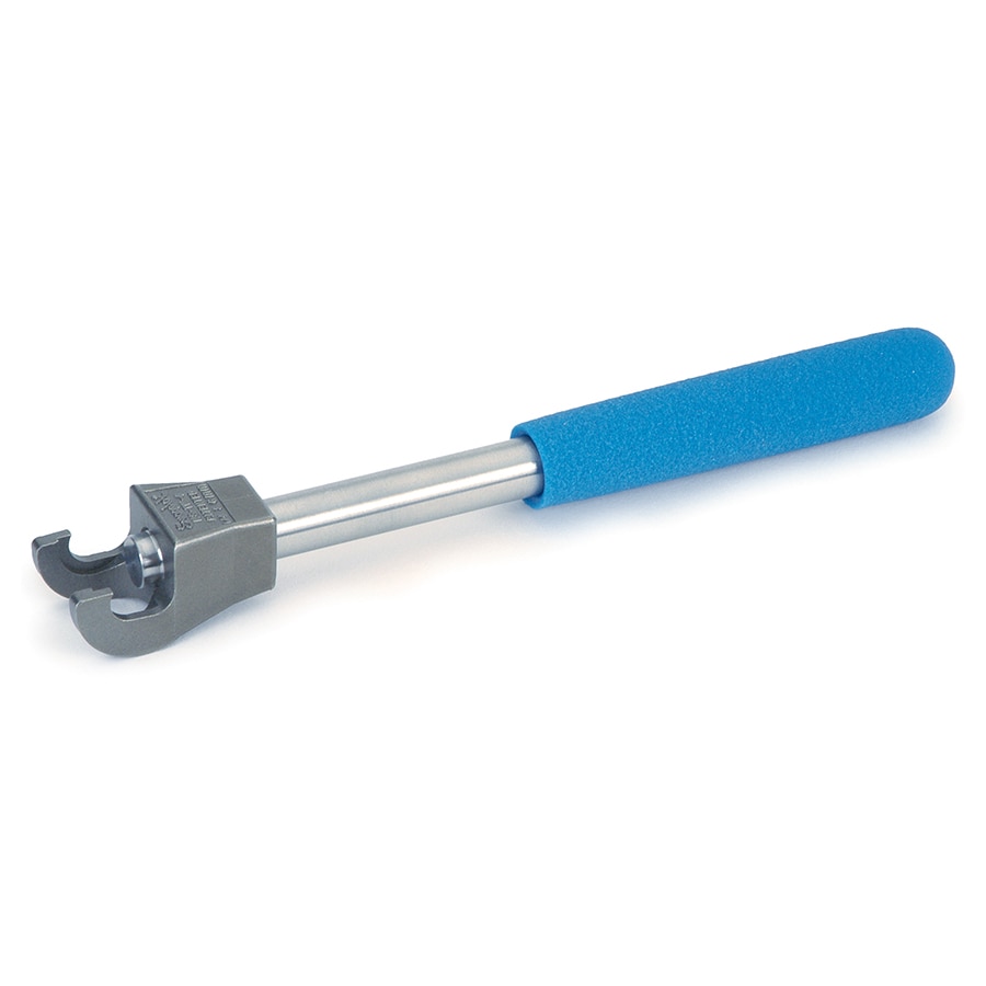
If you’re using a Tee fitting, it can be difficult to hold it in place and tighten the top fitting. While you can angle the wrench across the body to hold it steady, a better option is to use a Tee wrench (cat.# 22623).
Figure 5: Angled Wrench and Tee Wrench on Tee Fittings
Angled Wrench

Tee Wrench

From there, the amount to tighten the fitting is important, and is something that I found I didn’t understand as well as I thought. Swagelok’s recommendation is to tighten 1/16” and 1/8” fittings by ¾ of a turn, and 1/4” fittings by 1 and ¼ turns (see figure 5). I have been installing compression fittings by feel, and while I’ve been pretty close on the smaller sizes, I definitely haven’t been going more than a full turn for most ¼” fittings.
Figure 6: Proper Tightening for Compression Fittings >3/16”

Another way to ensure proper tightening is to use a gap inspection gauge, which can be used to measure how close the nut is to the fitting. We offer a gauge that works for ¼”, ½”, and 3/8” (cat.# 22624), but other sizes can be purchased from Swagelok. I went and checked some ¼” fittings I’d installed with the gap inspection gauge and sure enough several of them were under-tightened. Even though they were all leak free, better tightening will likely make future connections seal more consistently.
It can be tempting to overtighten fittings if leaks are found, but that can cause several issues. On the fitting side, it can flare out the fitting where it meets the ferrule, making it difficult or impossible to remove or reinstall fittings. An example is shown in figures 6 and 7.
Figure 7: Comparison of a Damaged, Flared Fitting to a Normal One
Flared Fitting

Normal Fitting

Another issue that can happen is the compression of the tube itself. Since the end of the tubing should be bottomed out when installing, overtightening can squeeze the tubing and cause it to bulge out ahead of the ferrule, especially with softer tubing like copper. This can cause the tubing to get stuck in the fitting, making it difficult to remove. The fitting itself can be deformed as well, making it difficult to re-seal it if new fittings are installed. An example is shown in figures 8 and 9.
Figure 8: Tubing Stuck in Fitting Due to Overtightening

Figure 9: Correctly Tightened Tubing (Left) and Overtightened Tubing (Right) Showing Bulging Due to Over-Compression of the Ferrule

Tune in for the next blog where I cover compression fitting repair techniques.